In this tutorial the Stellaris LM3S6965 Evaluation board will be used to demonstrate a simple PWM (Pulse Width Modulated) example. This is part of a larger project I am working on, which is not covered in this tutorial but will be posted at a later date.
When carrying out any programming on the Stellaris LM3S series, I would highly recommend downloading the Peripheral Driver Library PDF, this contains details of all the functions used to control the on chip peripherals. The current release at the time of writing is spmu019p.pdf and can be downloaded from here
You will also need to install StellarisWare which is the Texas Instruments library files for the Stellaris and also contains code examples. Viewing the various libraries while in code composer can be very useful to fully understand what each function does. The 2 files for the PWM are pwm.h and pwm.c, which can be found in the StellarisWare installation folder, in my case this C:/StellarisWare/driverlib/
The first thing that needs to be setup with the Stellaris is the system clock, the following code below uses the external crystal oscillating at 8MHz.
// Set the system clock to run directly from the crystal
	SysCtlClockSet(
			SYSCTL_SYSDIV_1 | SYSCTL_USE_OSC | SYSCTL_OSC_MAIN
					| SYSCTL_XTAL_8MHZ);
Next the PWM peripheral needs to be enabled, there are 3 PWM modules on the LM3S6965 evaluation board. For this example PWM0 will be used, which is located on GPIO port F.
// Enables PWM pheripheral
	SysCtlPeripheralEnable(SYSCTL_PERIPH_PWM);
// Enables GPIO port F where PWM0 is located
	SysCtlPeripheralEnable(SYSCTL_PERIPH_GPIOF);
The next step is assign a pin type to the GPIO, there is a specific function to configure a pin or pins for use by the PWM peripheral.
//PWM0 is on GPIO port F, pin 0
	GPIOPinTypePWM(GPIO_PORTF_BASE, GPIO_PIN_0);
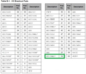
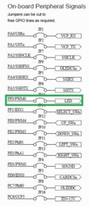
PWM0 and GPIO pin 0 on port F is assigned, this combination was used for the PWM as it allows the onboard status LED to be controlled by varying the brightness, and will also allow a meter to be used to measure the frequency from the PWM. The image below and left shows the I/O Break Pads, the image on the right the on board peripheral signals, both are extracts from the LM3S6965 evaluation board user guide.
After the GPIO is setup the PWM can now be configured. As stated before there are 3 PWM modules on this particular microprocessor, only 1 is being used in this example PWM0. Each PWM generator module has a 16 bit counter, 2 PWM comparators, a PWM signal generator, a dead-band generator and an interrupt/ADC-trigger selector. This program example will just produce a simple output using the up down counter.
PWMGenConfigure() is used to set the mode of operation for the PWM generator. The counting mode, syncronization mode, and debug behaviour are all configured. Once configured the generator is in a disabled state. A code snippet of this function is shown below.
// Configuring PWM Generator,
// \param ulBase is the base address of the PWM module
// \param ulGen is the PWM generator to configure.  This parameter must be one
// of \b PWM_GEN_0, \b PWM_GEN_1, \b PWM_GEN_2.
// PWM_GEN_0 controls PWM0 and PWM1
// \param ulConfig is the configuration for the PWM generator and uses a
// logical OR carry out the configuration
// Here PWM_GEN_MODE_UP_DOWN sets the counting mode to counting down and
// PWM_GEN_MODE_NO_SYNC sets the counter load and comparator update sync mode
	PWMGenConfigure(PWM_BASE, PWM_GEN_0,PWM_GEN_MODE_UP_DOWN | PWM_GEN_MODE_NO_SYNC);
PWMGenPeriodSet() is used to set the period of the PWM generator. Note the comment regarding the placement of this function with regards to PWMGenConfigure().
// **Should be called after PWMGenConfigure has been called as changes to the
// mode affect the period of the PWM signals produced**
// \param ulBase is the base address of the PWM module
// \param ulGen is the PWM generator to be modified.  This parameter must be
// one of \b PWM_GEN_0, \b PWM_GEN_1, \b PWM_GEN_2.
// PWM_GEN_0 controls PWM0 and PWM1
// \param ulPeriod specifies the period of PWM generator output, measured
// in clock ticks.
// Clock is set to 8MHz therefore the period is 125nS
// Therefore 333*125nS gives a frequency of 24.024kHz
	PWMGenPeriodSet(PWM_BASE, PWM_GEN_0, 333);
PWMPulseWidthSet() is used to set the width of the pulse for the specified PWM ouput. Note the comment regarding the placement of this function with regards to PWMGenConfigure().
// **Should be called after PWMGenConfigure has been called as changes to the
// mode affect the period of the PWM signals produced**
// Sets the pulse width for the specified PWM output.
// \param ulBase is the base address of the PWM module.
// \param ulPWMOut is the PWM output to modify.  This parameter must be one
// of \b PWM_OUT_0, \b PWM_OUT_1, \b PWM_OUT_2, \b PWM_OUT_3, \b PWM_OUT_4,
// \b PWM_OUT_5.
// \param ulWidth specifies the width of the positive portion of the pulse.
// With a period of 333, a value of 166 here should produce nice a square wave
	PWMPulseWidthSet(PWM_BASE, PWM_OUT_0, 166);
PWMGenEnable() is used to enable the timer/counter of the PWM generator.
// Enables the timer/counter for a PWM generator block.
// \param ulBase is the base address of the PWM module.
// \param ulGen is the PWM generator to be enabled.  This parameter must be
// one of \b PWM_GEN_0, \b PWM_GEN_1, \b PWM_GEN_2.
	PWMGenEnable(PWM_BASE, PWM_GEN_0);
PWMOutputState() enables or disables the PWM outputs.
// Enables or disables PWM outputs.
// \param ulBase is the base address of the PWM module.
// \param ulPWMOutBits are the PWM outputs to be modified.  This parameter
// must be the logical OR of any of \b PWM_OUT_0_BIT, \b PWM_OUT_1_BIT,
// \b PWM_OUT_2_BIT, \b PWM_OUT_3_BIT, \b PWM_OUT_4_BIT, \b PWM_OUT_5_BIT.
// \param bEnable determines if the signal is enabled or disabled.
// The parameter \e bEnable determines the state of the selected outputs.  If \e bEnable is
// \b true, then the selected PWM outputs are enabled, or placed in the active
// state.  If \e bEnable is \b false, then the selected outputs are disabled
// or placed in the inactive state.
	PWMOutputState(PWM_BASE, PWM_OUT_0_BIT, 1);
In this example a frequency of approximately 24kHz was generated, with approximately a 50% duty cycle. The image below shows a basic multimeter with a frequency counter, displaying a value which coincided with the example program, and 2 further images showing Oscilloscope traces with the PWM duty cycle at 50% and 15%.
Image with PWMPulseWidthSet(PWM_BASE, PWM_OUT_0, 166);
Image with PWMPulseWidthSet(PWM_BASE, PWM_OUT_0, 50);
Example Code
The link below contains the zip file with the complete C code, there is a small advert page first via Adfly, which can be skipped and just takes a few seconds, but helps me to pay towards the hosting of the website.


Hi, I am doing the same thing but with the port D and de PWM1. I don’t know why my code don’t work.
Hi,
Presume you have changed these function calls to read for Port D as follows:
// Enables GPIO port D where PWM1 is located
SysCtlPeripheralEnable(SYSCTL_PERIPH_GPIOD);
and also
// PWM1 is on GPIO port D, pin 1
GPIOPinTypePWM(GPIO_PORTD_BASE, GPIO_PIN_1);
PWM1 will still be controlled by PWM Generator 0. Are you able to produce a PWM output on Port F as in the example code?
Regards,
Ant